Automation lets you use the capabilities and features of Microsoft Office products, such as Microsoft Word or Microsoft Excel, in your Microsoft Dynamics NAV application.
Today we will implement Word Automation from a customer card in the Microsoft Dynamics NAV Windows client.
Note: The Microsoft Dynamics NAV Web client does not support automation.
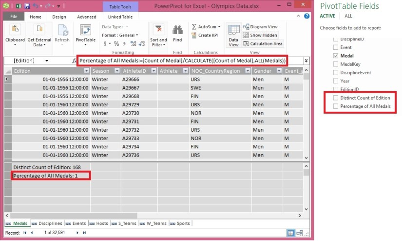
Most information that we need to transfer to Word for this example is in the Customer table. The Customer table contains a FlowField called Sales (LCY) that contains the aggregated sales for the customer.
In this example we are learning about Automation, so we will use the existing value. In a real customer installation, we would need to set up an appropriate date filter to get the sales for the past year only.
We also need to retrieve the information about our own company that we will use in the letterhead and in the greeting of the letter. This information is contained in the Company Information and User tables.
- The Automation server must be installed on the computer that compiles an object that uses Automation. If you must recompile and modify an object on a computer that does not have the Automation server installed, then you must modify the code to compile it again. We recommend that you isolate code that uses Automation in separate codeunits.
- Performance can be an issue if extra work is needed to create an Automation server with the CREATE system call. If the Automation server is to be used repeatedly, then you will gain better performance by designing your code so that the server is created only once instead of making multiple CREATE and CLEAR calls).
Performance can be improved by putting the code on the customer card because you do not have to open and close Word for each letter that is created in the session.
You can work around this problem. If Word is already open when it is called from the code, then the running instance is reused. You can manually open Word or do not close Word after creating the first letter.
We will extract and transfer data one customer at a time. We will also initiate this processing and the subsequent processing in Word from the customer card.
We will insert fields into the Word template and give these fields convenient mnemonic names that correspond to the names of the record fields that we are using.
To make this work, C/AL code must make two extra calls to Microsoft Office Word. You must call the ActiveDocument.Fields.Update method before using the fields. After you have transferred all the information, you must call the ActiveDocument.Fields.Unlink method. This ensures that you can successfully use the Word fields as placeholders.
In addition, while you can name the Customer or Address fields, you must reference them by indexing into the Fields collection of the document. This can make the C/AL code harder to understand.
Creating the Word Template for Use by Automation
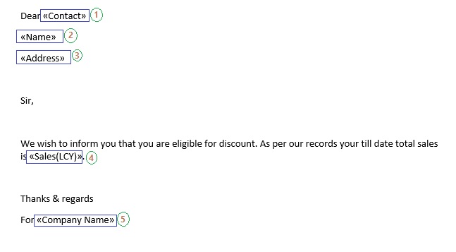
First, task is to create a Word template that we will use to create letters to customers that qualify for a discount. To create the template, we will add mail merge fields for displaying data that is extracted from Microsoft Dynamics NAV that you want included in the customer letter, such as the customer’s name, contact, and total sales.
You will create and save the template on the computer running the Microsoft Dynamics NAV Windows client, because you will configure the automation object to run on the client.
- On the computer running Microsoft Dynamics NAV Windows client, open Word and create a new document.
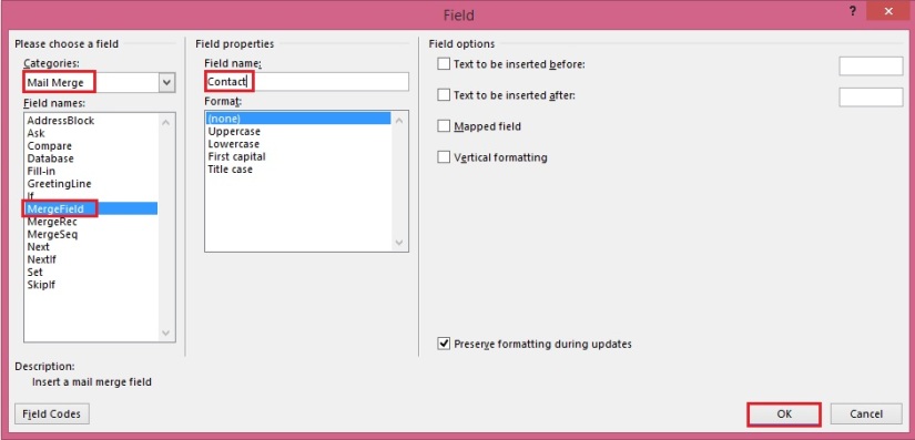
- Choose where you want to insert the fields. Then, on the Insert tab, in the Text group, choose Quick Parts, and then choose Field.

- In the Categories list, select Mail Merge.
- In the Field names list, select MergeField.
- In the Field Name box under Field Properties, type Contact. This field will display the name of your contact person at the customer site as taken from the Customer table.
- Choose OK to add the field.
- Repeat steps as above to add the remaining fields as follows:
| Field name |
Description |
Underlying table |
| Name |
The name of the customer. |
Customer |
| Address |
The address of the customer. |
Customer |
| Sales (LCY) |
The total amount that the customer has purchased from you. |
Customer |
| Company Name |
The name of your company. |
Company Information |
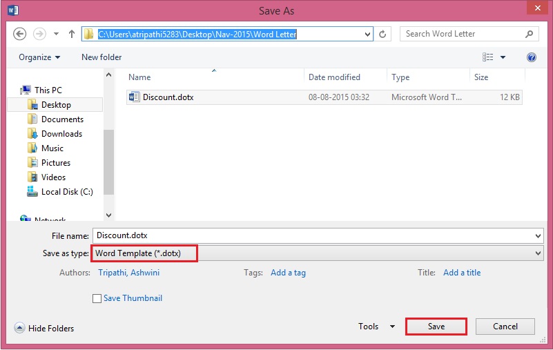
- Save the Word document as a template with the name Discount.dotx in folder of your choice.
Creating the Codeunit and Declaring the Variables
The next step is to create the codeunit that calls Word and creates the letter.
To create the codeunit
- In Object Designer, choose Codeunit, and then choose the New button to create a new codeunit.
- On the View menu, choose Properties to open the Properties window of the codeunit.
- In the TableNo field, choose the AssistEdit button to open the Table List window.
- In the Table List window, select the Customer table, and then choose OK.
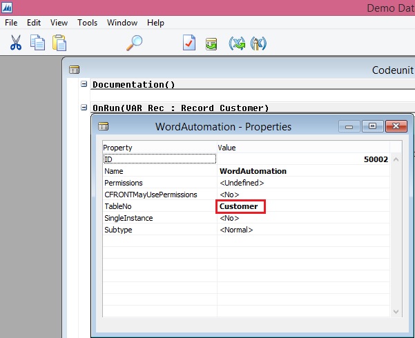
- Close the Properties window.
To declare the variables
- Choose the OnRun Trigger and on the View menu, choose C/AL Locals, and then choose the Variables tab.
- On a blank line, type wdApp in the Name field and set the Data Type field to Automation.
Note
When you create an Automation variable, some hidden events are also created for it. If you want to delete the variable, be aware that the events are also not deleted. This can cause issues if you then create a variable with the same name.
- In the Subtype field, choose the AssistEdit button. The Automation Object List window is displayed.
- In the Automation Server field, choose the AssistEdit button.
- In the Automation Server List, select Microsoft Word 15.0 Object Library if you are running Word 2013, or select Microsoft Word 14.0 Object Library if you are running Word 2010, and then choose OK.
- From the list of classes in the Automation Object List, select the Application class, and then choose OK.
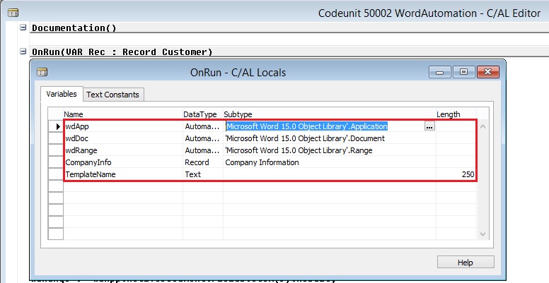
- Repeat steps above to add the following two Automation variables:
| Name |
Data type |
Subtype |
Class |
| wdDoc |
Automation |
Microsoft Word 14.0/15.0 Object Library |
Document |
| wdRange |
Automation |
Microsoft Word 14.0/15.0 Object Library |
Range |
- Add the following variables.
| Name |
Data type |
Subtype |
Length |
| CompanyInfo |
Record |
Company Information |
|
| TemplateName |
Text |
|
250 |
- Close the C/AL Locals window.
Writing the C/AL Code
Before you start writing the C/AL code that uses Automation, you must do some initial processing. You start by calculating the Sales (LCY) FlowField. Then, you check whether the customer qualifies for a discount. Finally, you retrieve the information from the Company Information and User tables that you use to fill in some of the fields in the letter.
To write the C/AL code
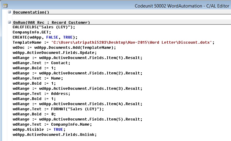
- In the C/AL Editor, add the following lines of code to the OnRun section.
| CALCFIELDS(“Sales (LCY)”);CompanyInfo.GET; |
- To create an instance of Word before using it, enter the following line of code.
| CREATE(wdApp, FALSE, TRUE); |
- This statement creates the Automation object with the wdApp variable.
- The first Boolean parameter in the statement (FALSE) tells the CREATE function to try to reuse an already running instance of the Automation server that is referenced by Automation before creating a new instance. If you change this to TRUE, then the CREATE function always creates a new instance of the Automation server.
- The second Boolean parameter in the statement creates the Automation object on the client. This is necessary to use this codeunit on a page in the Microsoft Dynamics NAV Windows client.
- Enter the following lines of code to add a new document to Word that uses the template that you designed earlier. If required, replace C:\Users\atripathi5283\Desktop\Nav-2015\Word Letter with the correct folder path to the template that you defined in the procedure.
| TemplateName := C:\Users\atripathi5283\Desktop\Nav-2015\Word Letter\Discount.dotx’;wdDoc := wdApp.Documents.Add(TemplateName);wdApp.ActiveDocument.Fields.Update; |
- Because the Add method of the Documents collection requires that you pass the path to the template by reference, you must set up the TemplateName variable to hold this information. You will get a compilation error if you put the path into the call as a literal string.
- The Documents property returns a Documents collection that represents all open documents. You can also see that the Documents collection object has an Add method, and that the Add method has the following syntax.
- expression.Add(Template, NewTemplate, Document Type, Visible)
- expression is a required argument, and it must be an expression that returns a Documents object. All the arguments are optional. You will use Template to open a new document that is based on your template.
- For the syntax in the C/AL Symbol Menu, note that the Documents property returns an object of type DOCUMENTS, which is a user-defined type. The property returns a Documents class or IDispatch interface. This information helps the compiler perform a better type check during compilation. The following statement can also pass both the compile-time and the run-time type checks.
- wdDoc := wdApp.Documents.Add(TemplateName);
- Finally, the Add method returns a Document class. While you did not need to declare a C/AL variable for the interim Documents class, you have declared a variable for the wdDoc return value,.
- The third line contains a call that must be made to ensure that the template works as intended.
- wdApp.ActiveDocument.Fields.Update;
Transferring Data to Word
Now you can transfer the actual data from the Customer record to the placeholder fields in the Word document.
You have set up the first three fields in the template so that they can contain the contact, name, and address of the customer and you can transfer the data.
To transfer data to Word
- Transfer the data by adding the following lines of code.
| wdRange := wdAPP.ActiveDocument.Fields.Item(1).Result; wdRange.Text := Contact; wdRange.Bold := 1; wdRange := wdAPP.ActiveDocument.Fields.Item(2).Result; wdRange.Text := Name; wdRange.Bold := 1; wdRange := wdAPP.ActiveDocument.Fields.Item(3).Result; wdRange.Text := Address; wdRange.Bold := 1; |
- You cannot use the fields directly as variables and make an assignment such as Fields.Item(3) := Address. Instead, you use the Result property of the field. This property returns the result of the field as a range. You place this range in the wdRange Automation variable that you declared.
- You then set the Text property of the range to the desired values, which is the name of your contact person and the name and address of the customer. Finally, you add bold formatting.
- The data you are transferring must be in text format. If it is not in text format, then you get a compilation error. wdRange.Text expects arguments to be of type BSTR, which maps to either Text or Code. This means that any data that is not Text or Code must be converted before it is passed to Word. To convert a field to Text, you use the FORMAT function. All the fields that are transferred in this step are in text format, so no conversion is needed and the FORMAT function is not used. However, in this example, you also need to transfer the Sales (LCY) field, which is a Decimal field. To see how to convert the Sales (LCY) field, go to the next step.
- To transfer and format the data from the Sales (LCY) field, add the following code.
| wdRange := wdAPP.ActiveDocument.Fields.Item(4).Result;wdRange.Text := FORMAT(“Sales (LCY)”);wdRange.Bold := 0; |
- To transfer the information from the Company Information table, add the following code.
| wdRange := wdApp.ActiveDocument.Fields.Item(5).Result;wdRange.Text := CompanyInfo.Name; |
- To complete the processing in Word, add the following code.
| wdApp.Visible := TRUE;wdApp.ActiveDocument.Fields.Unlink; |
- The first statement opens Word and shows you the letter that was created. The second statement makes the fields work as placeholders.
- Save and compile the codeunit
To-Do List
Although this code will work, you must add a few things to make it complete:
- We recommend that you do not use a hardcoded template name. You should keep the template name in a table, and the user should select it from a page. You can then have different templates for different types of letters that you want to send to your customers.
- You should add some error-handling code. For example, the CREATE call fails if the user does not have Word installed or if the installation has been corrupted. You should check the return value of CREATE and give an appropriate message if it fails.
- The user should get a message if the customer does not qualify for the discount. In the example, the codeunit closes without any message.
Calling the Codeunit from the Customer Card
The final task is to ensure that you can call the codeunit from the Customer Card page in the Microsoft Dynamics NAV Windows client.
To call the codeunit from the Customer card page in the Microsoft Dynamics NAV Windows client
- Open Object Designer, and then choose Page.
- Select the Customer Card page and then choose Design.
- On the View menu, choose Page Actions.
- To add a new action, locate the action container with the subtype set to ActionItems.
- Right-click the next line after the ActionItems container, and then choose New.
- In the Caption field of the new line, type Word Letter.
- Set the Type field to Action.
- With the new action selected, on the View menu, choose Properties.
- In the RunObject field, type codeunit Discount Letter.
Note
If you saved the codeunit that you created in the previous procedure under a different name, then substitute Discount Letter with the name that you used.
- Use the arrow buttons to make sure that the new action is indented only once from the ActionItems container above it

- Save and compile the Customer Card page.
To run the Customer Card and view the Word letter
- In Object Designer, choose the Page
- Select the Customer Card page, and then choose Run.
- In the ribbon, on the Actions tab, choose the Word Letter
The letter document opens in Word.

Next Steps
The letter that you have just created only contains five fields and sample body text. Before you can use this letter in an actual situation, you will need to add some more fields, such as the name and address of your own company, the date, and the currency code, and the main text of the letter. It will also need some formatting to make it look more attractive. If you alter the order in which the fields appear in the template, you must change the numbering of the fields in the codeunit to ensure that the correct data is inserted into the appropriate fields.
28.629409
77.432905